🎓 The evolution of transmissions: From crash boxes to I-Shift
As in my previous articles, this one explores the evolution of transmissions, with a specific focus on Volvo Truck variants. Remember, the aim here is not to delve into the technical details of how modern transmissions operate or are diagnosed (we cover this in the “Advanced” sections), but rather to highlight their evolution while staying true to their core principles. While technology may vary across different manufacturers, the fundamental concepts remain consistent. Transmissions have come a long way, from the early “crash boxes” to synchromesh systems, and eventually to the advanced Automated Manual Transmissions (AMTs) we see today.
▶ Early manual transmissions and the evolution to synchromesh
Manual transmissions of the early days required the driver to manually synchronize the input and output speeds to avoid grinding when shifting gears. This was done through controlled clutch and throttle movements. As technology advanced, synchromesh transmissions were introduced. These systems took over the task of synchronizing the gears, making gear shifting smoother and simpler for the driver.
🧩 Automated Manual Transmissions (AMT) and Geartronic
The next significant leap was the introduction of the AMT (Automated Manual Transmission), with Volvo’s Geartronic system leading the way. Essentially, Geartronic is a normal manual synchromesh transmission, but with electronic control. AMT’s can be operated as a manual or automatic without the need for a clutch pedal, while keeping a mechanical clutch system. The clutch cylinder/servo and solenoid valves are operated electronically, allowing the transmission to shift gears automatically. The Transmission Electronic Control Unit (TECU) receives signals from multiple control units, such as the Vehicle Electronic Control Unit (VECU), Antilocking Braking System (ABS), and the Engine Electronic Control Unit (EECU)/Engine Management System (EMS). Based on these inputs, the TECU controls the shifting process, from releasing the clutch to engaging the correct gear. After the shift, the system signals the EECU and VECU to allow the engine to accelerate back to normal driving speed.
💡 The I-Shift transmission: The combination of manual and automated systems
Volvo’s later innovations led to the creation of the I-Shift transmission, starting with the “B” generation. This transmission combined elements of both manual and Geartronic systems. While the Geartronic was a full synchromesh transmission, the I-Shift B generation only retained the synchromeshed “Splitter” and “Range” units while gears 1, 2 and 3 reverted to more simple “crash” gears – meaning the synchromesh units on these were removed. Although removing the synchromesh units saved weight and reduced moving parts, it also necessitated a new method to synchronize the input and output shaft speeds. To achieve this, a pneumatically operated brake system was installed at the front of the countershaft.
This was a complete re-design of the Geartronic system except for the continued use of an external clutch cylinder/servo. The operation was largely controlled by the TECU, which interpreted signals from other systems to manage the shifting process. It was a definite improvement on the Geartronic, however it was quite limited in its accessory capabilities.
Subsequent versions – the “C, D, E, and F” generations were refined further by combining the external servo and the release bearing into one internal unit, simply called the clutch cylinder. This negated the need for separate components ie: clutch servo, fork and release bearing. Improvements to the TECU itself has allowed for the increased number of applications that can now be used with the I-Shift transmission, such as concrete pumps and other specialised power take off (PTO) applications.
⚒ The basic operation of a transmission
Understanding how a transmission works, both in its mechanical and electronic forms, is key to diagnosing issues. The transmission is connected to the engine via the clutch. When the clutch is engaged (foot off the clutch pedal), the transmission’s input shaft rotates continuously, as it is coupled to the engine. When the clutch is disengaged (clutch pedal pressed), the input shaft stops rotating, breaking the connection to the engine. This is why a vehicle doesn’t move when a gear is selected and the clutch is disengaged.
🛠 The inner workings of the transmission
Inside the transmission, we have two shafts: the main shaft and the countershaft (also known as the cluster shaft). The countershaft holds fixed gears that rotate as one unit and are directly driven by the input shaft. As long as the input shaft is turning, the countershaft and its attached gears will rotate as well.
The main shaft, on the other hand, holds the selectable gears. These gears are always in constant mesh with their counterparts on the countershaft. As the gears are in constant mesh with the countershaft gears, they are free to spin on the main shaft by means of needle bearings or bushes. This ensures the main shaft and with it the output shaft, remain stationary when in neutral. Each gear on the main shaft has “dog teeth,” which interact with the “dog teeth” of a hub and sliding sleeve (selector sleeve) alongside it. The sliding sleeve’s hub is either press-fitted or spline-fitted to the main shaft, enabling it to rotate the main shaft when a gear is selected.
When a specific gear is selected, the selector fork moves the sliding sleeve, locking it into place with the dog teeth of the selected main shaft gear. This action directs the engine’s power through the engaged gear and out to the propeller shaft, driving the wheels.
The size of the countershaft and main shaft gear combination determines the speed and power ratio of the output shaft. Usually 1st gear on the main shaft is the largest gear which follows on to say that 1st gear on the countershaft is the smallest. This allows for more torque to be delivered to the output shaft and wheels for pull away and steep hill climbs. As we move up the gears the main shaft gears get smaller and the countershafts gears get larger. In heavy duty applications it is not unusual to find a crawler gear. This would then replace the 1st gear as the largest gear.
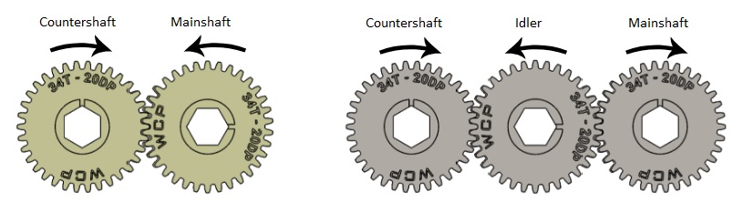
Reverse is achieved by the addition of an idler gear between the countershaft and the main shaft gear. The two shafts normally rotate in opposite directions to one another. The addition of the idler gear makes them rotate in the same direction, essentially turning the output shaft in the opposite direction to normal operation.
💻 The role of electronics in transmission operation
The basic operation of the transmission has remained largely unchanged despite the evolution of electronics. Whether it’s a traditional manual, Geartronic, or I-Shift, the core components remain the same, clutch, clutch servo, input shaft, main shaft, countershaft, selector forks, and dog teeth. What has changed is how these components are controlled.
The electronic systems now replace the mechanical inputs once required by the driver. Instead of manually operating the clutch and selecting gears, electronic signals control these processes. This means that while the core mechanics remain the same, the way they’re controlled has drastically improved, enhancing ease of operation and performance.
🔬 Diagnosing transmission issues
By examining the development from simple manual gearboxes to advanced automated systems, we can see the central role that electronics now play in making transmissions more efficient, reliable, and easier to use. The future of transmissions will likely see even more advancements in automation and electronic control, but the foundational mechanics will continue to provide the backbone for their operation. It therefore follows on to say that understanding the basic functioning of a transmission is crucial for diagnosing faults, especially in modern systems like the I-Shift. When we know the function of, and how each component interacts, we can better understand what the DTC’s (Diagnostic Trouble Codes) are trying to tell us, we can then apply our knowledge to troubleshoot problems effectively.
An example of this would be:
Numeric – MID 130 PSID 25 FMI 1
Text – Transmission System, Gears 1/R Engagement system, Value too low
If we look at this code we see a bunch of information and we need to interpret it. The onboard diagnostics and the laptop will give us both versions of the code, the numeric and the text. MID 130 tells us it’s the transmission system, PSID 25 tells us which part of the transmission, in this case 1st and reverse gear engagement and FMI 1 gives us information about the area of concern, in this case “value too low”. Its the “FMI” and its description that actually tells us the most about the DTC. The first 2 are quite simple, transmission and 1/R engagement, but what does “FMI 1” or “Value too low” mean. Simply put, the selector is not moving enough and more accurately, the amount of travel is less than the stored calibration data.
Combining our knowledge of the basic operation of a manual transmission and the information in the DTC we can safely say there is a mechanical issue inside the transmission preventing the 1st / reverse selector from reaching its fully engaged position. We can now use the diagnostic pc to run some tests, concentrating on the 1/R selector before dismantling the selector tower. The test results will give us a better idea of what is happening inside and what to look for when we do remove the selector tower.
In conclusion then, all the way through this article I have referred to the different evolutions of Volvo Trucks’ transmission, starting with the manual, then geatronic, I-shift B and then the more streamlined I-shift C, D, E & Fs’. What’s important to note is that all the variants are manual transmissions making use of a clutch, input shaft, main shaft, countershaft, output shaft, sliding hubs and sleeves, selector forks and selector shafts. The difference is the way the selector shafts are moved. The manual uses a cable setup connected to a gearlever whereas the AMT’s make use of electronic over pneumatic shift cylinders that move upon instruction from the Transmission ECU (TECU). Therefore if we understand how the basic transmission works, we can again use the reverse engineering method to diagnose faults with the electronic control system.