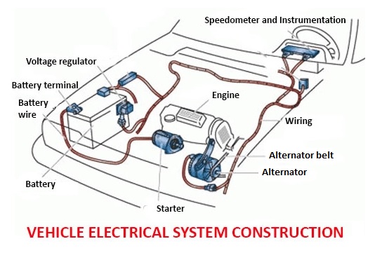
🔰 Lets get the basics and build a circuit
When novices first open a wiring loom, they are often overwhelmed by the jumble of different coloured wires, all tangled together without any clear beginning or end. This can seem intimidating, but it’s crucial to step back and understand what you’re working with.
One way to make sense of electrical systems is to think of them in terms of something simpler, like household wiring or even plumbing. While not directly related, these systems share the same fundamental principle: a circuit with a beginning and an end. When this circuit is broken, it cannot be completed and will not work.
💡 Analogies to understand circuits
Consider a plumbing circuit in your home. The main water supply is the starting point, and your kitchen sink tap is the endpoint. If the pipeline connecting these two parts is broken (say, due to digging in the yard), the water will leak out at the break and won’t make it to the sink. This is an example of an “open circuit.” However, when the pipeline is intact, water flows freely from start to finish, and this is considered a “closed circuit.”
Similarly, in vehicle electrical systems, there is always a starting point (usually the positive terminal of the battery) and an endpoint (typically the negative terminal). All of the components in between make up the specific circuit, and like the plumbing analogy, the circuit must remain complete for everything to work.
🔋 The role of the battery
The battery is the heart of any automotive electrical system, whether in traditional vehicles or electric vehicles (EVs). In modern vehicles, the most common battery systems are 12-volt and 24-volt setups:
- 12-volt systems are used in vehicles that don’t require a large amount of power, such as light-duty vehicles.
- 24-volt systems are used in heavy-duty vehicles, like trucks with large diesel engines, which need more power to overcome high compression ratios during engine start-up.
In some cases, you might see four 12-volt batteries connected in parallel to achieve higher power, but typically, 12-volt systems will use one or two batteries.
- Parallel connections: When two or more batteries are connected in parallel, all the positive terminals are connected together, and all the negative terminals are connected together. Each battery supplies current individually, which helps extend the battery life and capacity.
- Series connections: In a 24-volt system, two 12-volt batteries are connected in series by linking the negative terminal of one battery to the positive terminal of the other. This increases the overall voltage to 24 volts.
Most modern vehicles use a negative ground system, where the negative terminal of the battery is connected to the vehicle’s chassis. This allows the vehicle’s body to serve as the common ground, so you don’t have to run separate wires from each component back to the negative terminal of the battery.
Occasionally, you may encounter positive ground systems, where the positive terminal of the battery is connected to the chassis. In this case, the positive terminal serves as the common ground.
Similarly, the positive from the battery is connected to a central point in the vehicle, generally the fuse box. All the positive wires of the various circuits are routed here. In modern vehicles it is common to see multiple fuse boxes in a vehicle. This is to minimise the number of wires running in the chassis and bodywork.
🧱 Building a simple circuit
Let’s start by looking at a basic electrical circuit:
- Battery: The positive terminal of the battery is connected to one terminal of a light bulb (the globe).
- Wires: A wire is run from the other terminal of the bulb to the negative terminal of the battery.
- Complete Circuit: This forms a closed circuit, allowing current to flow, and the light bulb will light up.
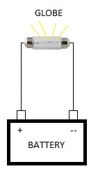
If you disconnect either of the wires – whether the positive or negative – the circuit will be open, and the light bulb will turn off.
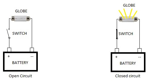
Let’s add a switch to control the circuit:
- A switch is placed anywhere in the circuit to open or close it. For this example, we add the switch in the positive wire.
- When the switch is in the off position, the circuit is open, and the bulb is off.
- When the switch is turned on, it closes the circuit, allowing current to flow and the bulb lights up.
❗ The importance of fuses
Fuses are essential for protecting electrical circuits from overloads or short circuits, similar to how circuit breakers protect household wiring. A fuse will “pop” or break the circuit if the current exceeds the safe limit, preventing damage to components or wiring.
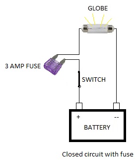
For our simple circuit, a 3-amp fuse is sufficient, as we’re only powering a single light bulb. The fuse should be placed between the switch and the light bulb. If a short circuit occurs, the fuse will blow before the wiring or switch gets damaged.
In modern vehicle systems, main fuses are typically located near the battery to protect the entire electrical system. We’ll explore more about these fuses in more complex circuits later on.
🌟 “Splicing” and adding a relay to the circuit
Relays are used to control high-power devices with low-power signals, such as turning on a spot light with a switch connected to the vehicle’s main beam circuit. Adding a relay prevents overloading the circuit.
Relays come in 4-pin or 5-pin configurations. For simplicity, we’ll start with a 4-pin relay. The basic components of a relay are:
- Coil Pins (85 and 86): These are used to activate the relay. Pin 85 connects to ground, and pin 86 connects to a positive signal.
- Switch Pins (30 and 87): These handle the current flow. Pin 30 is the current input, and pin 87 is the current output.
To add a relay to our simple circuit:
- Wiring the Relay:
- Connect a wire from the positive side of the battery to pin 30 of the relay.
- Connect a wire from relay Pin 87 to the positive terminal of the spotlight.
- Connect the spotlight’s negative terminal to the negative side of the battery or a common ground.
- Connect a wire from relay Pin 85 to the negative side of the battery or a common ground.
- Connect a wire from relay Pin 86 to the output side of the switch between the fuse fuse and bulb.
In the diagrams below you will see circular symbols on the wires. These are known as splices and are points at which 2 or more wires join. The splices indicate where in the circuit the wires join. There is a splice on the positive between the battery and the switch, between the fuse and the bulb and on the negative between the battery and the bulb. Take your time to look at the diagrams and make sure you understand them according to the instructions above.
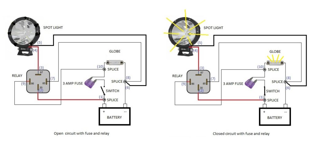
Now, when you turn on the switch, it will activate the relay, which closes the circuit and allows current to flow to the spotlight. The light will illuminate once the relay is activated.
Just like in any electrical system, you should always include a fuse for protection. In this case, place a fuse between pin 87 of the relay and the spot light to protect the wiring and ensure safe operation of the circuit.
📦 Conclusion:
Above, we have essentially created 2 separate circuits integrated into 1. This is considered a complex circuit and as you will find out later is the basis of IC’s (integrated circuits) in electronics. We went from a very simple circuit and evolved it into 2, more elaborate circuits. As the need for more applications arise, bigger more powerful batteries are needed and more circuits are added or “spliced” in. Each additional circuit requires its own set of wires. Importantly, it is essential to isolate only the circuit we are interested in and try as much as possible to ignore all the other wires that do not form part of the circuit we are dealing with. Of course having a full, application specific wiring diagram comes in very handy when dealing with complex systems. More on these later.
At the core of all electrical systems is the concept of the closed circuit – a loop that allows current to flow from the battery, through components like switches and bulbs, and back to the battery. From this simple foundation, more complex systems are built, adding relays and fuses to manage the flow of electricity safely and efficiently. Understanding these basic principles is crucial for diagnosing and troubleshooting electrical issues in vehicles. In the next stages, we will explore more advanced topics, like electronics, but the basic concepts will always remain the same.